The 15m part of our beam has been QRT for a while, likely due to a broken balun. It is a quite involved process to take the mast down for maintenance, so we have relied on temporary solutions to be active on 15m. Typically, that means setting up our portable 15m vertical on the roof without the tuner, as the tuner is only rated for 150 W.
This has worked great in the sense that we have gotten DX in all directions and that the alternative would be to try without 15m. However, we expect that this could have worked even better. Our portable vertical 15m (and our other commonly used verticals for 10m and 20m) have 4 quarter wave radials. This makes the antenna resonate in the band, but is suboptimal when the radials are not elevated. Our roof is not exactly ground, but not exactly air either, so we guess reducing the influence of this “ground” would improve performance. It would also be nice to have a radial-free antenna for portable trips.

We could of course elevate the ground plane, but we do have tall enough glass fiber masts to do something even better: Make a vertical dipole. Vertical dipoles are twice as tall, but that is only 7.5 m on the 15m band. One problem is that traditionally they are more difficult to feed. We would need another mast to hold up the coax so that it is normal to the antenna elements. However, there is a way around this that allows us to use only a single mast: Coax shield half-wave dipoles.
There seem to be two common approaches for this, and both seem to be more popular for VHF/UHF antennas than HF antennas. One is the so-called bazooka antenna, where we fold the outer conductor of a coax cable quarter of a wavelength back onto itself. Then, the folded-back part is the lower element, the remaining center conductor is the upper element, and the encapsulated coax feeds the antenna at the center. The other option is the Flowerpot antenna, where we don’t use an extra shield on the outside of the coax, but the outside of the usual coax shield. The currents on the outside of the shield are entirely separated from the feeding currents on the inside of the shield due to the skin effect. We still need the outside to be a quarter wavelength long, but the trick is to “end” it with a choke on the coax. The top element is just a single conductor. Often a wire, but it is also common to strip the shield of a coax and just use the inner conductor.
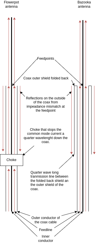
The bazooka antenna is not really just an element on the outside of a coax, it is very much coupled with the outer conductor. The trick is that the outer shield forms a sleeve balun with the inner shield by being an open quarter wave long transmission line stub. The problem with this is that the velocity factor of this transmission line stub depends on the sheath of the coax, which is typically undocumented. Without the proper instruments to measure this, we opted for the flower pot antenna as we expected it to be easier to handle the unknowns.
One of the unknowns would be the choke, but we based the design on the excellent work of G3TXQ. We lacked the setup to measure our choke, but 9 or 11 turns of RG-58 on 2x FT240-52 seemed to be quite wideband. We opted to try it and just hoped that the margins would be so large that we could just blindly use it. We acquired an FN25, which according to the advert, would equate to two stacked FT240-52s. Just what we needed.
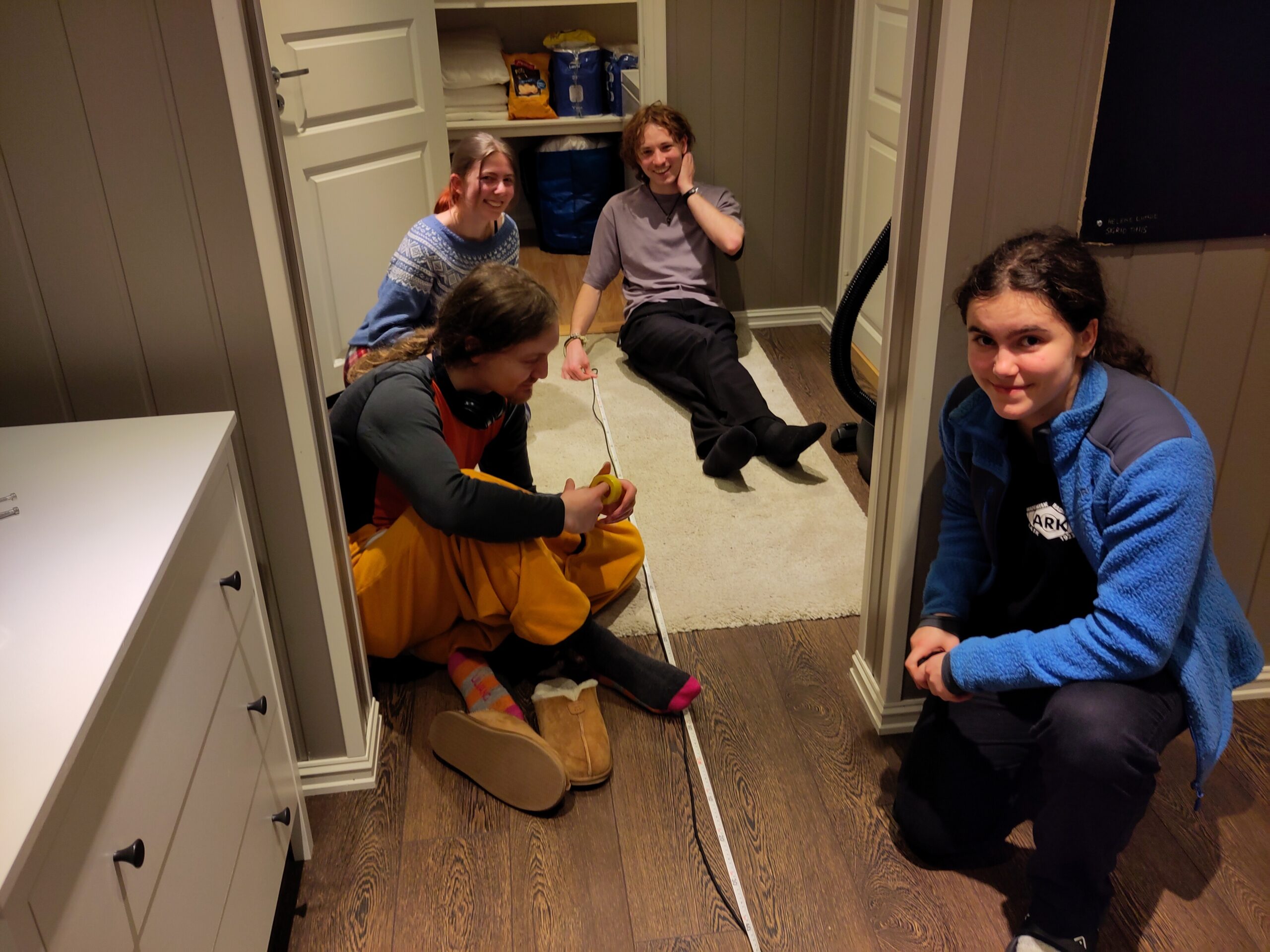
At our cabin trip in the beginning of February, we gathered a mix of new members and established members to attempt building this. We started out with a suitable length of unknown coax from our cable box that looked like RG-58. We opted to use the center conductor as the top element and thus needed to cut of the outer conductor of the coax. After some experimentation and one failed attempt, we managed to get off the outer conductor while leaving most of the dielectricum intact. We left it as structural support for the inner conductor, and to give a more predictable velocity factor. Assuming that it was close to the velocity factor of the cable, we set it to 0.67. The downside of leaving the dielectricum is the increased loss, but we deemed it acceptable.
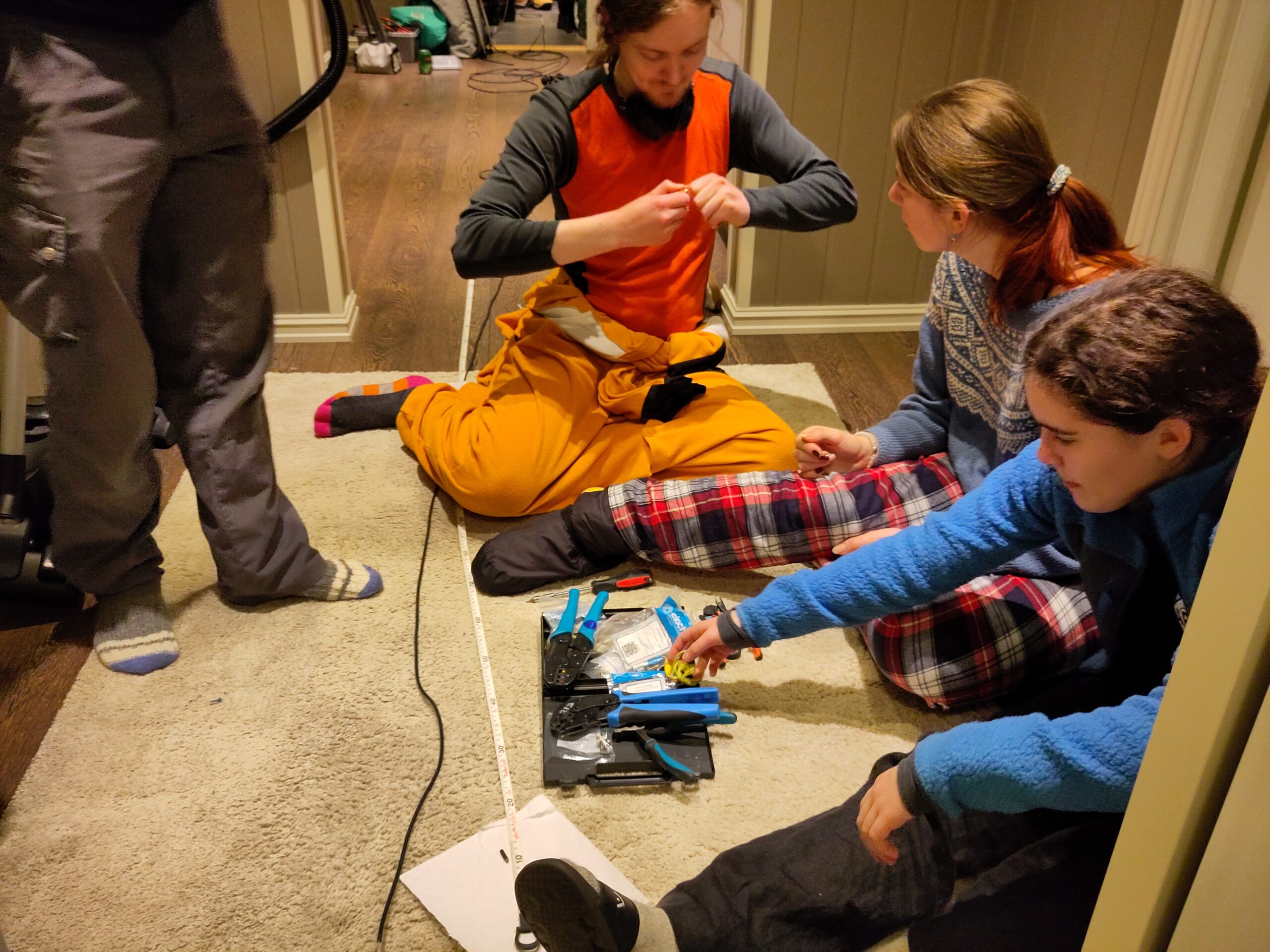
We tried to measure up a quarter wavelength from the start of the stripped outer conductor to the start of the choke, but we were unsure where in the choke we would say it started. We opted to choose the first winding of the coil, aware that we might have to shorten it later.
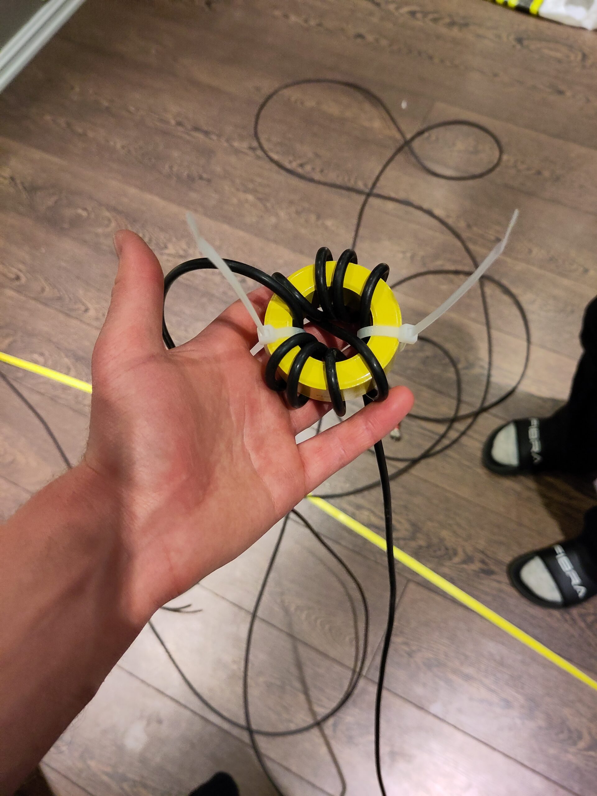
Winding took a while with the long coax, but at the end we fastened the windings with white cable ties. Then someone pointed out the similarity with a bee, with the white cable tie wings and black cable over yellow ferrite. A bee also seemed fitting for to find at a flowerpot antenna.
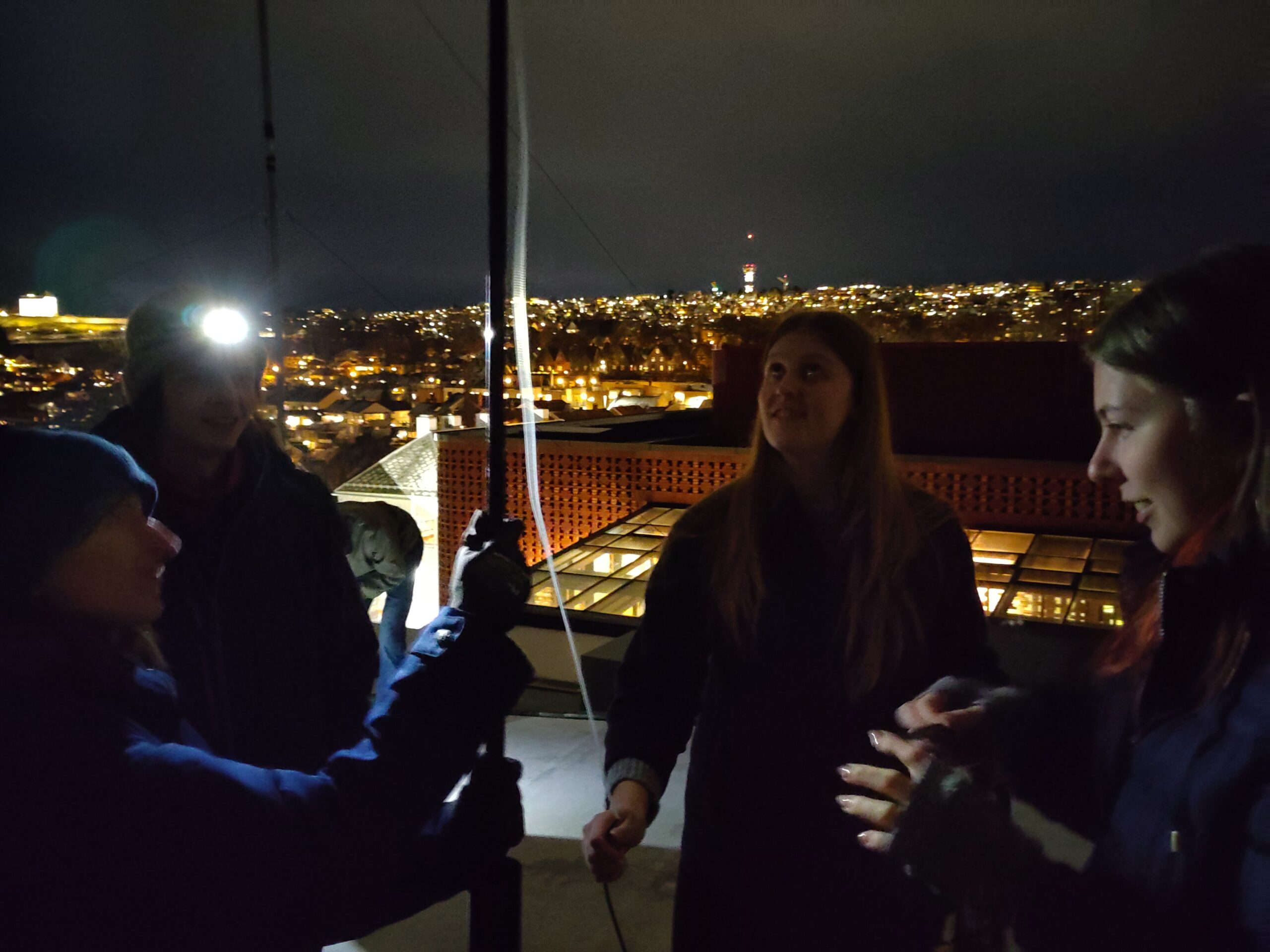
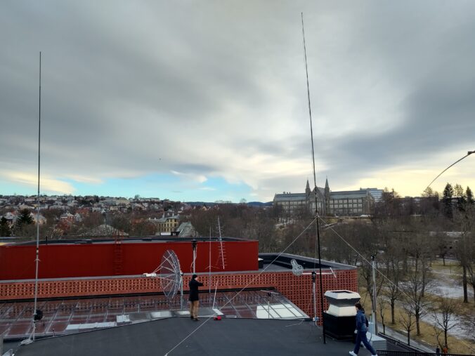
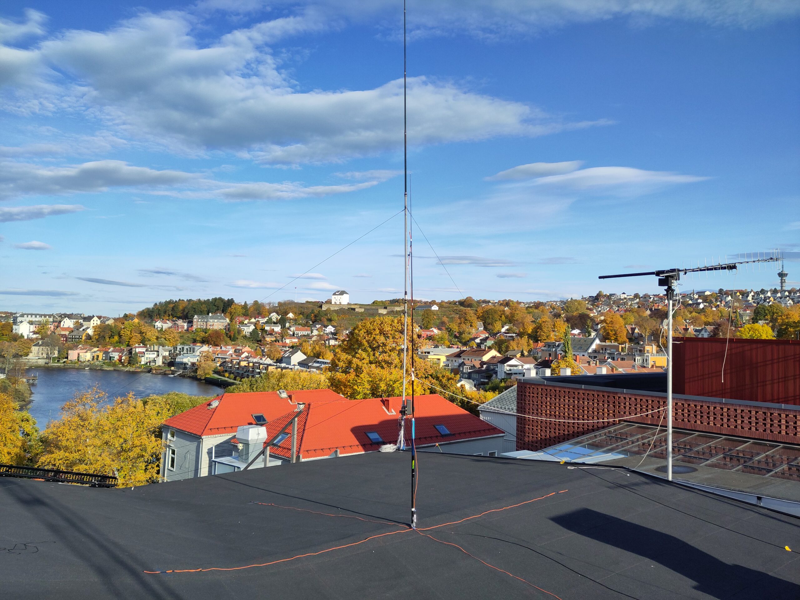
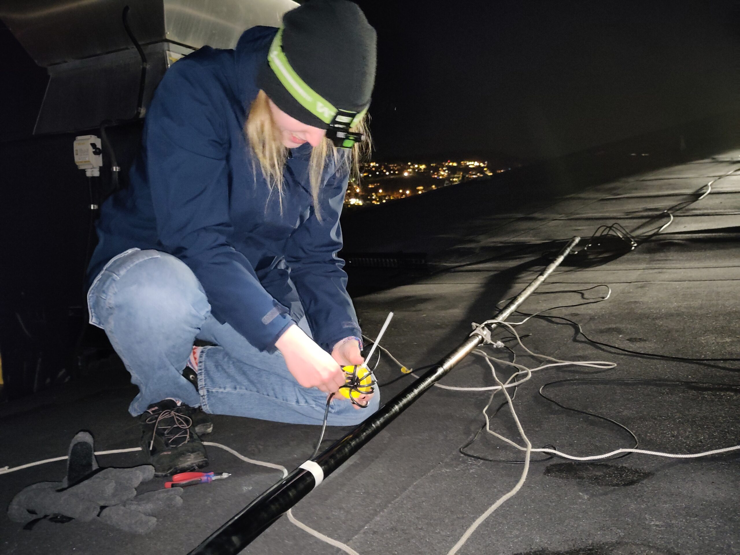
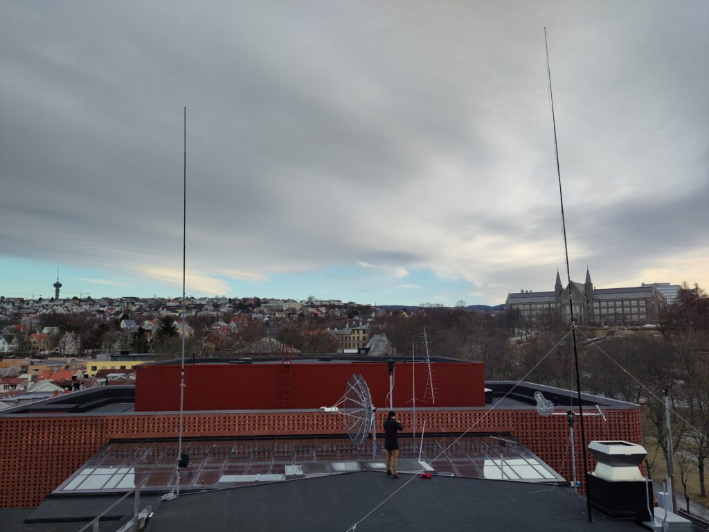
The following Monday, we set it up on the roof of Samfundet, with the intention of tuning it. To do this, we taped it to a glass fiber mast, erected it on the roof, and measured the SWR. Then we adjusted the length by moving the choke and tried again. This turned out to be quite a cold, iterative process, but we eventually got the SWR dip at the right place. First, it was only down to 2:1, but it improved when we moved the antenna further away from the other antennas on the roof.
The Friday after, we set the antenna and our old quarter wave vertical up before CQ WPX RTTY. The idea was to test them against each other, to see which one was the best. After tuning both of them to resonance, we used our FT-891 to reach out to the reverse beacon network. We got no response with 5 W, so we used 100 W for both antennas. We first called 3 times on the quarter wave vertical and then 3 times on the flowerpot.
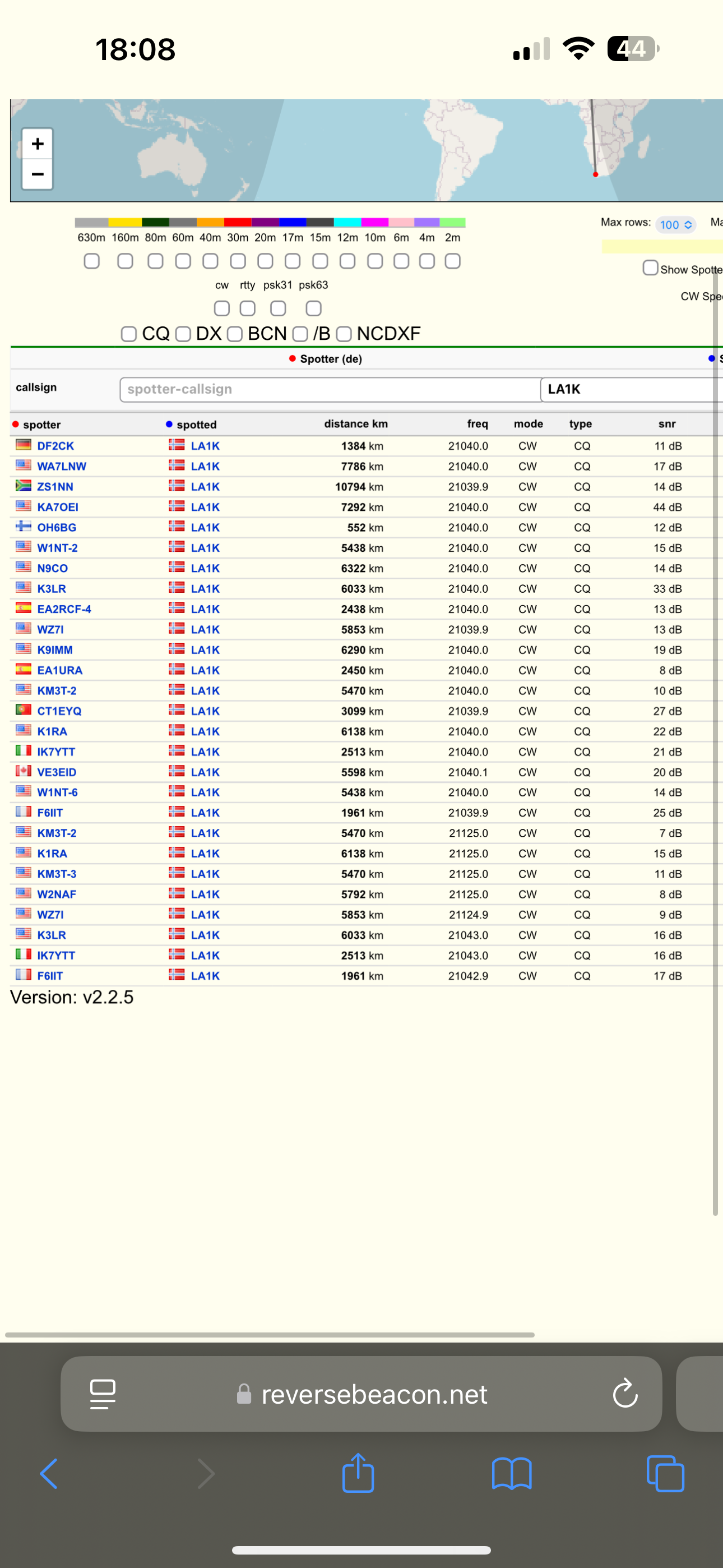
The results indicated a clear advantage to the flowerpot, compared to the quarter wave vertical. It was spotted by 19 RBN stations, compared to the vertical’s 5 spots. Of the stations that spotted both, the difference in reported signal strength was 4-7 dB. We made a mistake and tested the vertical outside of the CW band. It is not given that all RBN stations listen there, so the results might be skewed. Still, the dB reports were favorable.
During the contest, we got a slight indication that there might be some common mode current below the choke, which indicates that it is not good enough. However, it anecdotally worked very well and gave us a lot of QSOs.

I think LB5DH fixed the common mode currents by changing the amount of turns in the bee choke. Afterwards, I measured the antenna using our VNA, and it turned out to be on the inductive side when measured at the end of the coaxial cable. I used https://www.will-kelsey.com/smith_chart/ to design a suitable L-match, and found that the series inductor was so small that it could be skipped, thus ending with a small UHF-UHF connector device with a roughly 100pf capacitor in parallel. This should in theory make it into a 45 ohm pure resistive load, and the SWR measures to roughly 1. I tested it gradually up to 100W, with no noticeable arcs or SWR spikes over 2.