Most of the club’s activities fall within NTNU’s semesters. Many students leave Trondheim for internships or vacations during the summer. Fortunately, this does not include everyone. We have a lot of equipment, and as with all other equipment, it needs maintenance. Much of it is best done outdoors, preferably in summer weather. Therefore, we gathered some of the people still in Trondheim for two days of maintenance work, primarily on the equipment we use on Field Day.

On the first day, we set out to test a new balun for our 60m wire dipole and to get an overview over our coax cables. Our 60m antenna was next to useless last Field Day, and we suspected a broken balun. Therefore, LA2QUA, LB1DJ, and LB0CJ found a new replacement balun, which we wanted to test before the upcoming Field Day.

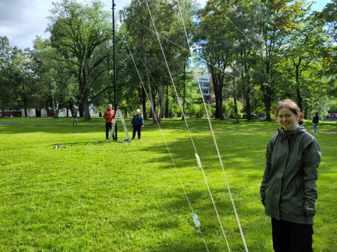
We tested it at a parking lot near our remote storage at Dragvoll. Using two 12 m HD Spiderbeam poles, we got the antenna about 10m off the ground. This was sufficient for us to see that there was a clear dip in the SWR. It was a little low in frequency, which indicates that the antenna was a little too long. However, this is influenced by several factors, including height over ground and quality of ground. Both of these will likely differ on Field Day, so we deferred any adjustments until then.

The other thing we wanted to do on day one was to get an overview of our coaxial cables. Over the years, we have collected a wide variety of coaxial cables of different types, quality of termination, and lengths. Each Field Day we find that we have enough, but end up using some bad cables and have to debug the signal chain.

Thoroughly testing all aspects of a cable is quite work intensive, so to get through them all in one day, we settled for a reduced version with the following goals:
- Get an overview of all the cables, including their type.
- Measure their lengths.
- Visually inspect the quality of termination.
This did not include a test of cable loss, but we assumed that cables that looked ok were also electrically ok. We measured the length of each cable by using the TDR(Time Domain Reflectometry) function of LA8ITAs NanoVNA.

We found that we have a lot of cables with termination in only one end and some cables that are poorly terminated. However, we also found that we have sufficiently many that are both good and long enough.

On the second day, we wanted to upgrade the 80m vertical from last year and retune the spiderbeam yagi, which has not happened since 2016. Both are quite manpower-intensive operations, but LB1DJ got a big group together to try both simultaneously.

2023 was the first year with our current full-size 80m vertical, and the prototype we used then was not very robust. We soldered the element and the four radials to a chassis connector. We just taped both elements and radials to the mast for strain relief. This was very quick and easy, but only helped when the antenna was up. The rest of the year, it was crammed down in a box, and when we found it this summer, the solder point had broken.

To make the center point more robust, LB5DH 3D-printed housing for the chassis connector with built-in strain relief. We expect this to be easier to set up and
also to provide cover from light rain. LB5DH and LB0CJ soldered the antenna to the chassis connector and mounted it to the 3D-printed support. It mostly worked well, but the mounting ring was too wide and had to be helped with excessive amounts of tape.

The other thing we wanted to try with the 80m vertical was to adjust the lengths of the elevated radials. Last year they were not tuned, only measured up to an approximate velocity factor.

We tried to shorten the radials by about 3 meters to see what the response would be. Maybe we would get two dips, one from the resonance of the radials and one from the resonance of the element? This is not sound antenna theory, but it did not stop us from trying. The result turned out to be that the single dip just moved up in frequency and out of the band. Then it seemed pretty evident that we needed some other analysis to decide on the radial length, and we left them at the length we found them at. After all, the antenna already had a quite distinct and well-placed SWR dip in the band with the original radial lengths.

The spiderbeam yagi was tuned adequately in 2016, but it has gradually slipped out of tune over the years. The antenna is constructed from wires strung up with fishing lines. The lengths of these are given in the manual, but in practice, we found that we also had to fine-tune them.

It is not entirely clear how this tuning changed over the years, but it seemed to have worsened. Either the fishing lines have elongated, or the endpoints have slipped. It was not yet critical on all bands, but it had progressed so far that the edges of the 10m band and 15m band now had a SWR higher than 2.5.

Adjusting all the lengths turned out to be quite a tedious job, which took several hours of measuring up and adjusting. When they were done, the SWR indicated that the antenna was good.

The weather offered both rain and sun and while it was sunny, we had a break and BBQed. All in all, this turned out to be both a productive and enjoyable day. Thanks a lot to LB0CJ, LB5GH, LB0BJ, LB5FJ, LB0ZI, LB0RI, LB3SG, LB2BI, LB4FI, LB5DH, Øyvind and especially LB1DJ for bringing us all together.


Leave a Reply