Recently, we were made aware of plans another radio club has to install a voice repeater at the Vassfjellet mountain summit where our beacons reside. They have performed a survey at the site, and it seems they will try to set up a six meter repeater there.
As mentioned in previous posts, we operate four beacons at the site. The beacons operate in the 6 m, 4 m, 2 m and 70 cm bands.
We don’t know too may details from their survey, as they haven’t made contact with us. We became aware of it by getting hints of a blog post they wrote after doing the survey. The survey was primarily performed with an FT-857D and a four element phased vertical dipole. They claim that the beacon splatters all over the 2 m band – resulting in 2 m being unusable both for repeaters and other users at the summit.
We take complaints and criticism seriously, and we want to work with all interested parties to find good solutions. We immediately went up to measure the beacons properly, and to address any issues with unwanted or excessive radiation.
Our survey indicates that LA2VHF, or any of our beacons, are not the cause of the interference, and that the issues observed by the other club are spurious components generated by some receivers when exposed to high signal levels.
Survey equipment
Our own survey was performed with an R&S FSH3 portable spectrum analyzer, a reference 2 m dipole antenna, and a set of different 2 m ham radio transceivers as control (FTM-350, TH-D72E, VX-8DR, VX-5R).
The 2 m beacon (LA2VHF)
The current incarnation of LA2VHF was installed in 1999/2000, so it has been operating for about 20 years. The exciter is semi-commercial, based on a modified AIS-transmitter board. We know it has some phase noise close to the carrier, and that it is not capable of fully suppressing the FM modulation at the start of every “dit” and “dah” in the CW sequence. The added FM modulation leads to a slightly wobbly sound.
To check the purity of the beacon, we attached it directly to the spectrum analyzer via 60 dB of attenuation. Samples were taken using the max hold function of the spectrum analyzer, and sampled until all spurious signals reached maximum level.
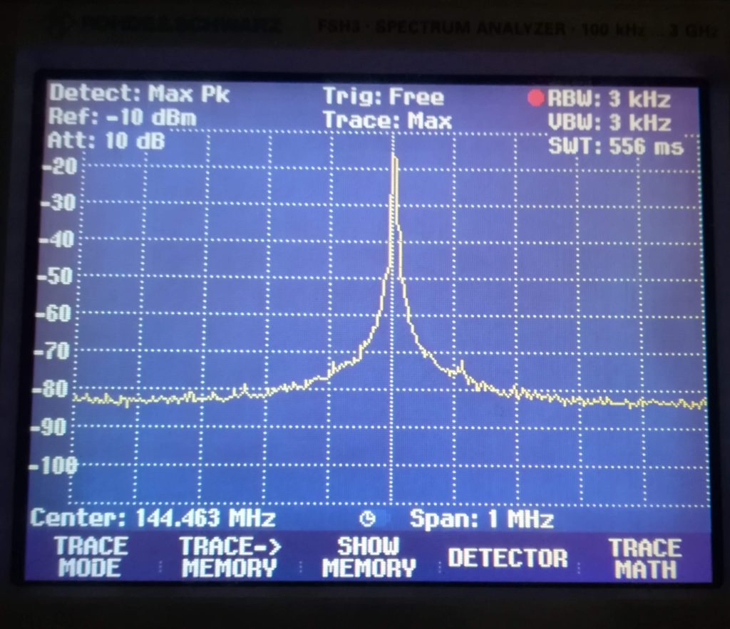
60 dB attenuated LA2VHF, 1 MHz span (143.963 MHz to 144.963 MHz) 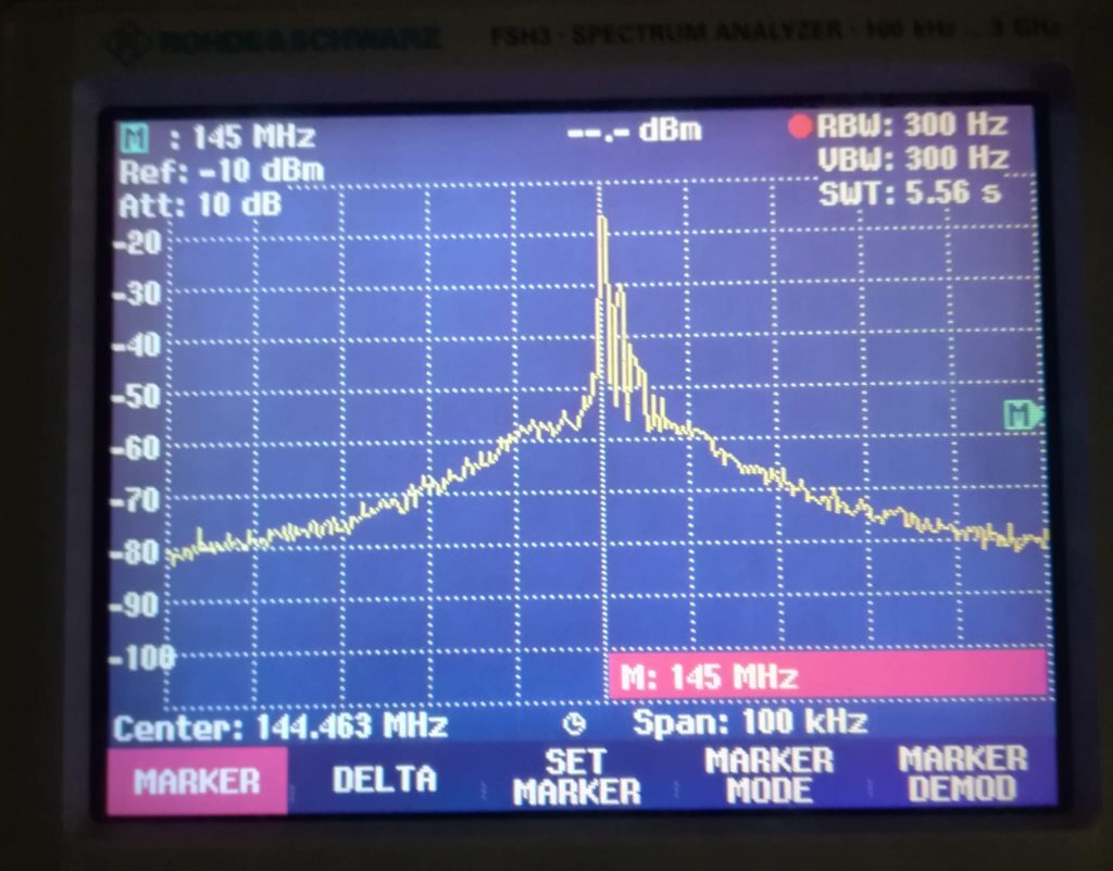
60 dB attenuated LA2VHF, 100 kHz span (144.343 to 144.543 MHz)
After correcting for the attenuation at the spectrum analyzer input, the phase noise is found to be better than -140 dBm once 100 kHz off from the carrier.
With 100kHz span (right picture), we clearly see the FM modulation component in the upper sideband from the carrier. We also see that the FM portion is not unreasonably wide, with a deviation of approximately +5 kHz. Finally, the phase noise 10 kHz off from the carrier is roughly -95 dBm.
Since the beacon has a phase noise below -140 dBm at 100 kHz it is safe to assume that it is not the cause of the issues observed by the other radio club. Only the best transceivers available on the market can boast a sensitivity rating of -140 dBm in the VHF section.
Handheld transceiver behavior at Vassfjellet
While doing our measurements at Vassfjellet, we also took the opportunity to get some clarity on the issue observed with handheld transceivers. From 40 years of operating beacons at the site, it is well known to us that some 2 m radios are susceptible to strong interference at the beacon site, while others are not.
To make controlled tests, we turned off the beacons, and powered them one-by-one to see what might be causing the issue. Interestingly, the transceivers that have noise issues in the 2 m band still experience the same noise when the 2 m beacon LA2VHF is turned off. In one of the transceivers, careful inspection revealed that the CW sequence actually belongs to LA2SIX.
With strong signal levels, there are many potential sources of saturation or intermodulation in a receive chain. One source is that quite a few modern rigs have a first intermediate frequency at frequencies such as 48.6 MHz and 68.4 MHz. As we operate beacons at 50.488 MHz and 70.063MHz, these may inject directly into the mixer, and cause wideband problems.
Experiment
To prove that a strong signal out of band is capable of causing such issues we set up an experiment in the lab.
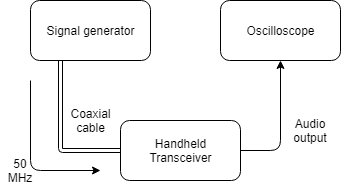
A signal generator was used to generate a leveled 50 MHz tone with an output power of -15 dBm into a Yaesu VX-5R handheld transceiver. The audio output of the transceiver was monitored using an oscilloscope. The VX-5R was operated in narrow FM mode, tuned to a frequency of 145.0 MHz and set to squelch level 4. As seen in the photo below, turning the generator on and off brings the squelch wide open. We also repeated the experiment with less output power, and got similar results, but less repeatability once the 50 MHz tone power was low enough.
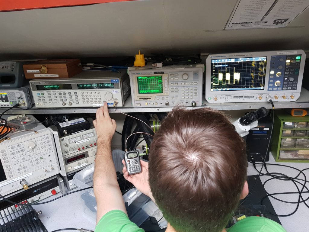
This experiment shows the rudimentary functions of the fault. In order to fully diagnose the interference issue, we would need direct access to the various stages of the receive chain.
Some theoretical notes
In order to see that the signal levels from our lab experiment is in line with what might be expected at the site, we must perform some calculations.
The Friis’ equation allows us to calculate how strong the beacon signals are at some point away from the transmitter. In this case, the original survey was done at a distance of 127 meters from the beacon antenna, with a 4-element stacked dipole array. The beacon antenna is a 10 element yagi, pointing at 15 degrees. The angular distance between the beacon main lobe direction and the survey site is 47 degrees.
We estimate 6dBi gain in the vertical plane from the stacked dipole, and a loss of somewhere around 20dB due to polarization. The beacon antenna gain is, conservatively, 10dBi in the front direction, with about 8dB less at 47 degrees.
Friis’ equation:
where: is the power at the receiver end (dBm)
-
is the transmitter power (dBm)
-
is the transmitter antenna gain (dBi) in the direction of the receiver
-
is the receiver antenna gain (dBi) in the direction of the transmitter
is the wavelength (meters) is the distance between the transmitter and the receiver (meters)
We fill in the measured data from the test site:
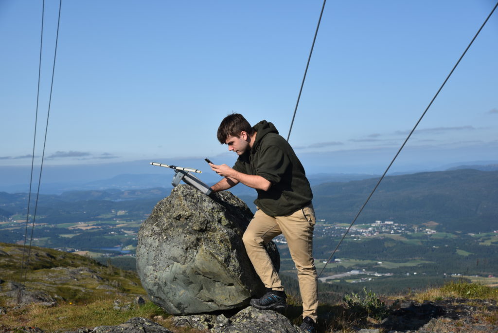
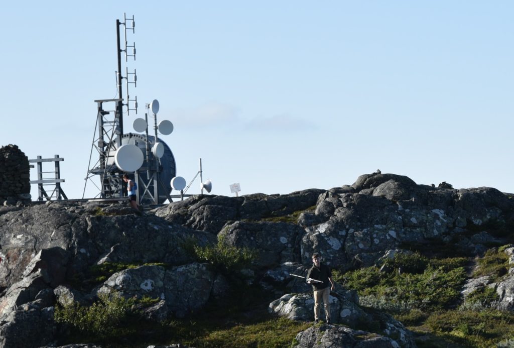
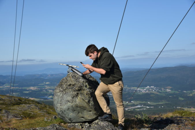
The theory was verified by direct measurements at 144.463 MHz which yielded about -8 dBm at the position seen in the photo below:
Similar calculations for 6 m and 4 m yield received results on the order of -10 dBm to 0 dBm (~S9+90 dB), assuming – 10 dB gain in the stacked dipole antenna. This means that our 4 m, 6 m and 2 m beacons are all capable of delivering powers that are beyond what we used to reproduce the issue in our lab experiment.
Conclusion
In conclusion, the beacon LA2VHF is not the source of the problems observed by the other radio club. The problems relate to wideband immunity issues within the receive chain of some radios when exposed to very high signal levels. In general, these issues are best solved by sufficient filtering, or attenuation at the receiver input.

Leave a Reply