Over the past couple of weeks we have been trying to listen in to the Fox-1 amateur satellites using our VHF/UHF array. While we were getting some receptions, the performance was not what we would expect from such a large array. For the 2 m downlink the results were similar to what could be achieved using a handheld Arrow antenna and a small FM transceiver. On the uplink on 70 cm, we were having issues with our IC-9100 reporting intermittent high SWR while the antenna was rotating.
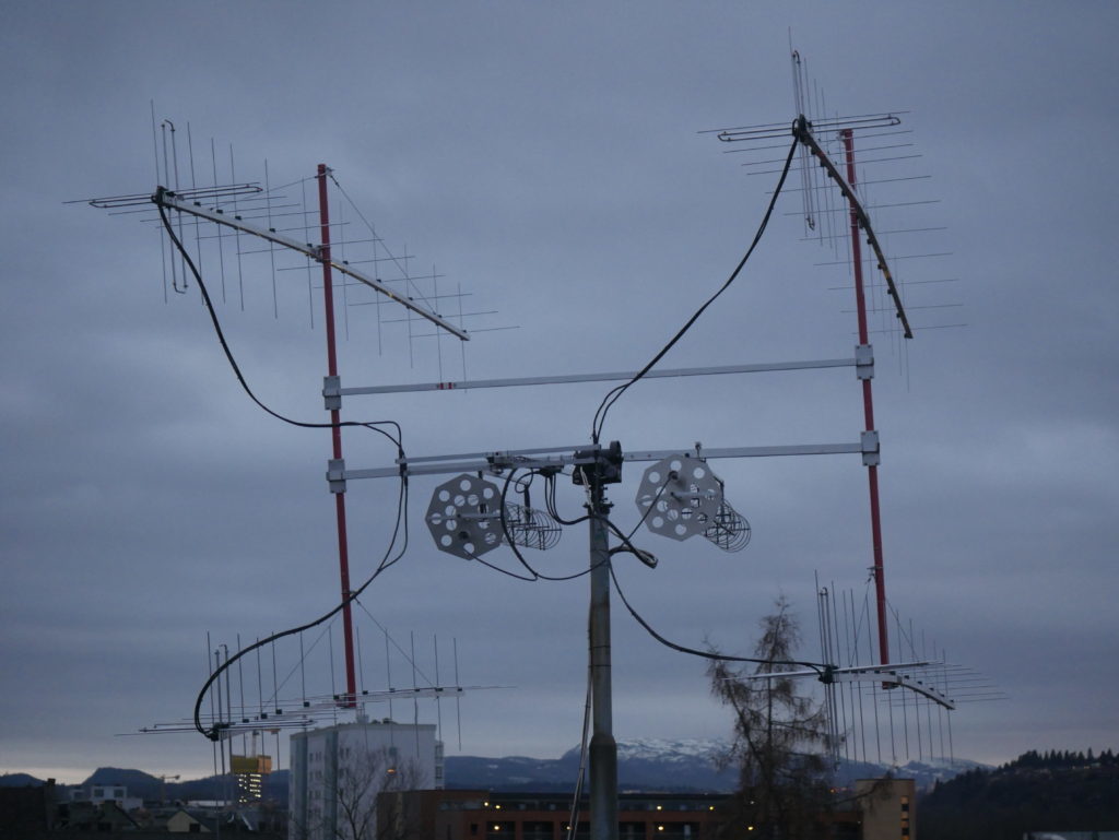
The VHF/UHF Array.
We have had a streak of nice weather lately, meaning that we could get started on our annual spring overhaul of the antenna park. With a list of symptoms at the ready, we systematically set to work on the VHF/UHF array. First order of business was lowering the mast.
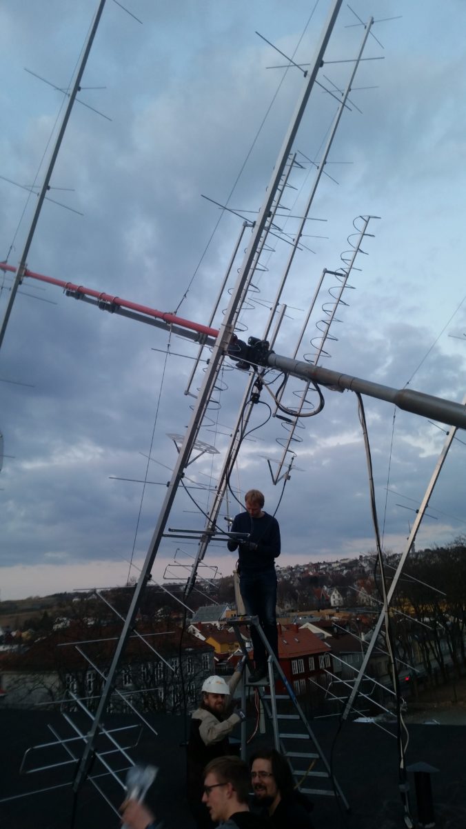
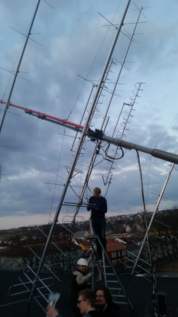
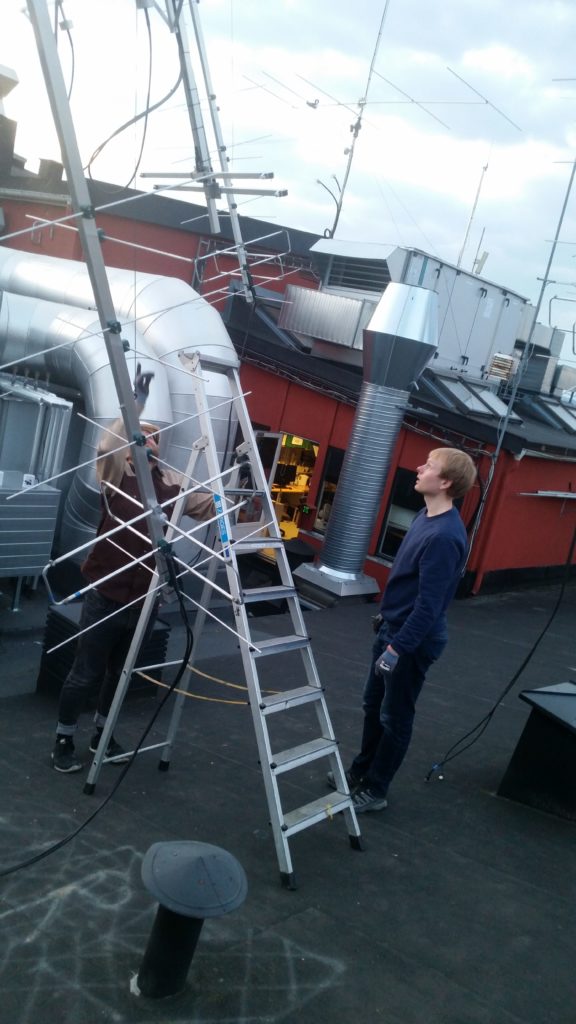
- VHF/UHF Array maintenance in progress.
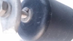
On 70 cm we have a two-stack of Wimo Helix 70 antennas. The antennas have not seen much use for the past couple of years, so the current state was somewhat unknown. Upon closer inspection it was discovered that the fastening bolt that fixes the spiral part of the helix to the input connector was missing the low side nut. This meant that the antenna would bounce up and down and sometimes lose contact with the connector, giving it ample cause to demonstrate high SWR during rotation. When the VHF/UHF array was updated two years ago, the fastening nut was probably forgotten. Since the author only measured the SWR of the 70 cm array while it was standing still, the issue went unnoticed for another two years, oups!
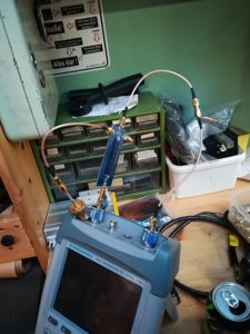
- On bands above 2 m we use an overcomplicated SWR bridge on our FSH-3 spectrum analyzer.
- The culprit connection missing a nut.
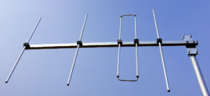
Our 2 m setup is a four-stack of 22 element dual polarized 144-LFA yagis from InnovAntennas. Using our AA-170 antenna analyzer we started by checking the SWR of the vertical and horizontal parts of the array. To our dismay, both vertical and horizontal SWRs were in the 10s, meaning that something was very wrong. Each phasing line was then separated from the 4:1 combiner in order to evaluate the input match of each individual antenna. When the first antenna maxed out our antenna analyzer with a 10:1 mismatch, we worked with an initial theory that the tuning structure had come loose. After removing the “tuning trombone” for closer inspection, we discovered that there was a large accumulation of water within, particularly for the vertical elements.
- A close up of the “tuning trombone” for an InnovAntennas LFA yagi. Credit: InnovAntennas.
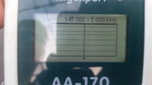
- 10:1 SWR reading on a AA-170 Antenna analyzer.
To prevent future buildup of water, we decided to drill some small holes in the trombone to allow the water a way to escape. Satisfied with our effort, we excitedly went back to check if the antenna would tune back to 1.1:1 SWR like it had originally.

YR.no weather statistics for Trondheim.
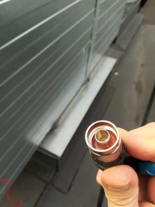
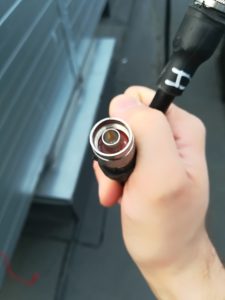
This was when we discovered the real villain of this week’s blogpost – thermal cycling and connector displacement. For the phasing harness a Westflex 103 variant with temperature rating from -15°C to 80°C had been selected. The temperature handling, or lack thereof, has caused the center pin of the N-connector at 6 out of 8 phasing lines to retract and/or skew to the side. We have a major rework job ahead of us…
- Retracted center conductor.
- Retracted and skewed center conductor.
After speaking to some of the older members of the club, this has been apparently been a recurring issue for us, particularly on beefy cables with solid centre conductors. In the past both retraction and expansion has been problematic. One story even claims to have had the N-connector center pin of a heliax-type coax pinned to a wall on a sunny day.
For now we are working with InnovAntennas to see what can be done about our predicament. On the positive side we have learned the importance of temperature rating for coaxial cables, and we may get to do a blogpost on manufacturing phasing harnesses in the near future


0 Comments
1 Pingback